
Atikokan Amateur Radio Club
Serving amateur radio operators and
providing emergency communications for Atikokan
and area
All material copyright © Atikokan Amateur Radio Club
E-
Snail mail:
P.O. Box 2106, Atikokan, Ontario P0T 1C0
VE3RIB repeater
Atikokan, ON
147.120 +
- WIRES-
x node 50878
VE3RIB-
144.390 (APRS)
VE3RIB-
144.390 (APRS)
VA3EOA station
Atikokan EOC
- VHF radio
- HF radio
- APRS digi
- Winlink & digi modes
VE3YIB station
Atikokan Airport
- Club station
- VHF and HF
Winlink RMS
VA3EOA


GE MVS Mods
By Warren Paulson, VE3FYN (Updated 20 February 2014)
IRLP Wiring
Introduction
The GE MVS radio is easily available on e-
While the power output is fixed, a quick modification allows you to reduce it as low as five watts for QRP operation. I've done this on two of my radios that are used only to access the local repeater.
You will need to locate or build a programming cable and software, or pay the price to have it done. Other than that, you'll find this a sound radio for these applications.
The manual
Download the original GE MVS manual here. This will provide operating information,
and in-
Go to our GE MVS Manuals page for technical manuals on this radio.
The model numbers
On the bottom of the radio is a silver tag with "COMB" then a number/letter sequence, and also "SER#" and a number/letter sequence. There is also some FCC data. What we're concerned with is the "COMB" data. This will tell you the band, frequency range, power output, number of channels, etc. The website has a complete chart, so I won't repeat it here. Note that many eBayers selling MVSs don't know what they have, so get the combination number off them and find out for yourself before bidding.
Opening the radio
Most of these mods are found on the bottom side of the radio. To access it, flip the radio over, and remove the two screws at the front of the metal plate. Simply flip the plate off, and expose the pc board.
The low-
 Ignition-
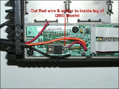
sense Mod
Open the underside of the radio. Clip the red power lead about two inches from the board. Strip a little insulator off, and solder the red wire to the topmost (in the picture) lead on the regulator. This simplifies your electrical hookup. Note F901, the little green fuse. It is discussed further below.
The little green fuse
Open the underside of the radio. To the right of Q903 mosfet, you'll see what looks
like a green resistor. (It's already removed in the picture below.) It may or may
not have resistor-
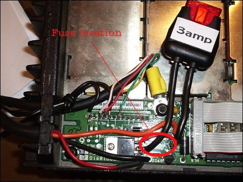 I have found these fuses hard to find, and annoying to replace. So, I replaced it
with a fuse holder. Remove the fuse, and solder short leads of wire to each hole.
Solder a fuse holder to these leads, and insert a 3 amp fuse. Alternatively, one
lead of the fuse holder may be soldered to the centre lead of the MOSFET. All my
MVS radios are in fixed locations. If you are using your radio in a car, you may
want something a little more robust than that, but you get the idea.
I have found these fuses hard to find, and annoying to replace. So, I replaced it
with a fuse holder. Remove the fuse, and solder short leads of wire to each hole.
Solder a fuse holder to these leads, and insert a 3 amp fuse. Alternatively, one
lead of the fuse holder may be soldered to the centre lead of the MOSFET. All my
MVS radios are in fixed locations. If you are using your radio in a car, you may
want something a little more robust than that, but you get the idea.
(The ignition sense mod photo, above, shows the F901 fuse quite well.)
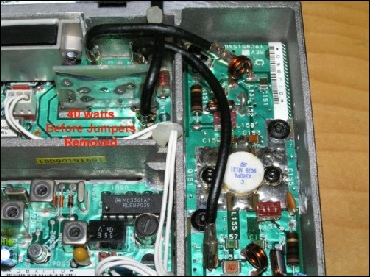
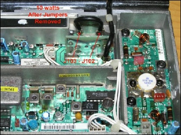
The low-power mod
If it applies to you, there's an easy mod that reduces the power output on the radio. This is the topside of the radio, at the back. Modifying the jumpers as described in the photos below will reduce the power output from 40 watts to ten watts. Backing off the trim pot (see adjustments below, will reduce output to five watts.
|
|
|
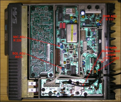
Adjustments
There are several trim pots on the top side of the radio offering adjustments, as indicated in the photo.
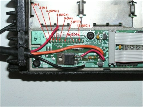
The option connector
On the System Board, you'll see a row of 13 pins. They are shown in the photo below, with the relevant pins labelled. The manual shows all pins and their purpose.
If you are running a TNC or interface (like a SignaLink) that requires power, connect
-
Audio from the radio is #3. The audio level from pin #3 varies depending on the volume
setting of your radio. Set the volume level where you want it for proper audio levels
into the computer, and leave it. I have found that even at its lowest setting, the
audio-
The MVS volume setting does not go down to 0, which is I've rigged a switch that bypasses the speaker and runs the audio through an 8 ohm resister to create a mute function. The manual indicates that to create a mute function, solder a switch that shorts #10 to ground. When #10 is shorted to ground, the speaker is muted. Output levels to #3 are not affected. However, #10 works as a COS indicator, which is useful in many applications. (#10 will go to +5vdc when a signal is received.)
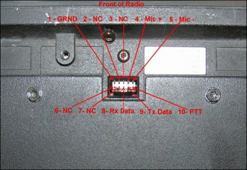
The mic connector
The mic connector has the same functionality as the option connector. Pins are shown in the photo below. Be careful. Shorting certain pins with power on will blow the internal fuse.
Other GE-MVS sites
There are other good GE-
- Hall Electronics (good model number chart)
- N0RQ
- IRLP.net
Thanks to Scott, VA3EXT for all his help teaching me many of these mods, and for many of the photos in this article.
Bypassing the power switch
In certain situations, you may want to bypass the power switch. This will ensure that the radio is always on, and that it will turn on automatically in the event of a power failure, once power is restored. (Note, that a feature of the MVS is that it will power up to the channel is was set to when it turned off.)
To set a GE-
This applies to UHF and VHF models.
Errata
R513 in this photo is not the squelch. It adjusts the audio level from the RF (receiver) board to the audio board. It should be left nearly fully clockwise for proper squelch operation.
The squelch pot is accessed through a hole on the audio board (inverted, on the left of the photo). It is labelled.
Thanks to Bill, K4OOO for pointing this out. (A new photo will be uploaded shortly).