
Atikokan Amateur Radio Club
Serving amateur radio operators and
providing emergency communications for Atikokan
and area
All material copyright © Atikokan Amateur Radio Club
E-
Snail mail:
P.O. Box 2106, Atikokan, Ontario P0T 1C0
VE3RIB repeater
Atikokan, ON
147.120 +
- WIRES-
x node 50878
VE3RIB-
144.390 (APRS)
VE3RIB-
144.390 (APRS)
VA3EOA station
Atikokan EOC
- VHF radio
- HF radio
- APRS digi
- Winlink & digi modes
VE3YIB station
Atikokan Airport
- Club station
- VHF and HF
Winlink RMS
VA3EOA

The Hardware
The interface needs to do three things:
- Send clean audio from the radio to the computer.
- Send clean audio from the computer to the radio.
- Trigger the radio’s PTT (push to talk) function when needed.
Now, here is where I differ from many other authors on this subject…
To Isolate or Not to Isolate?
Most articles on this subject will have you isolating all three lines so that there
is no electrical connection between the radio and the computer. This generally involves
using an opto-
This circuit provides the following features:
- Some isolation of the PTT line, using a MOSFET, which has a high impedance gate, thereby limiting (not eliminating) any voltage or current travelling from one device to the other.
- Elimination of any DC signals on the audio lines, using a capacitor. The chosen capacitor
also reduces low-
frequency audio. (The packet protocol used by APRS uses tones of 1200 and 2200 Hz. The chosen capacitor attenuates signals below these frequencies, and specifically any 60 Hz hum you may have from your mains.) - Simplicity and low-
cost.
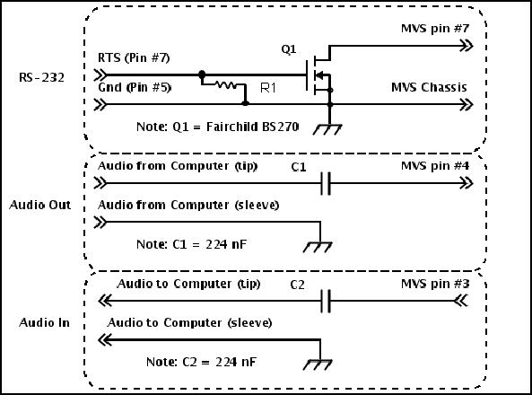
Schematic
The left shows the connections at the computer end.
The right shows the connections inside the GE-
All ground connections should be made at both the computer and radio side.
The value of R1 should be around 10K ohms. This resistor pulls the FET gate to ground, ensuring PTT won’t be triggered when the serial cable is disconnected.
Interface Functional Description
The interface must do two things: send audio back-
On the the radio, PTT is triggered by shorting pin #7 to ground. However, AGWpe triggers
PTT (on the left audio channel) by setting the serial port’s RTS line to high. This
causes it to go from -
If you don’t have any capacitors, a straight audio connection will work. However,
these capacitors do two things. First, they eliminate any DC from travelling through.
Any value of capacitor larger than about 200 nF will achieve this. (Much smaller,
and the signal will be attenuated.) At values around 200 -
Note that the capacitor will reduce the signal level to some degree. You may need
to use the computer’s more sensitive mic input rather than line-
Board Construction
The interface can be built on a small circuit board, and mounted inside the radio.
The pinout of the BS270 MOSFET is at right. The capacitors are non-
The MOSFET, when on, is fully saturated, so it won’t generate any heat. (No resistance, no heat.)
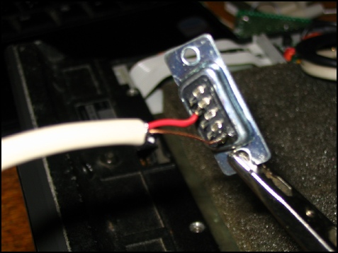
Only two connections are required on the serial plug. Pin #7 is the RTS line, and pin #5 is ground. If you are using a 25 pin plug, use pins #4 and #7 respectively.
Note that AGWpe can be configured to operate two radios. To do this, wire the DTR pin as well, which will act as PTT for the second radio. This is pin #4, or #20 on a 25 pin plug.

Pinout of the BS270. There is an internal reverse-
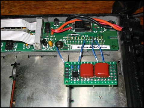
Here, the board is nearly finished, with the connections to the radio shown. Note
that the radio should not be powered-
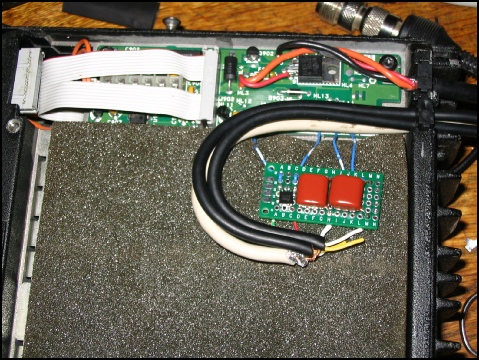
The finished product. I covered both sides of the board lightly with electrical tape to prevent any shorts. The lid of the radio holds the board down against the foam.
AGWpe uses the left audio channel for the first (or only radio.) This is the tip of the 1/4” plug. The lower sleeve is the ground, while the centre sleeve is the right channel.